
ZENNARO® has developed its own structure becoming a leader in manufacturing transformers of the following type:
Two manufacturing plants in Marghera (Venice) and a relevant export share are a guarantee of continuity and development.

Since the beginning, Zennaro® has always focused on constant quality upgrading in all sectors: planning, production, technology and organization.
Zennaro® transformers are designed to meet all the most recent national and international standards such as IEC, ANSI/IEE, CEN/ CENELEC, BS, DIN/VDE.
Since 1997 Zennaro® has been a certified company according to UNI EN ISO 9001 standards able to supply a wide of range of highly reliable products and a high quality service.
Since 1999 Zennaro® is a qualified supplier for the Italian Electricity Company (ENEL) with HV/LV distribution transformers, transformers forming neutral (TFN), earthing transformers and reactors.
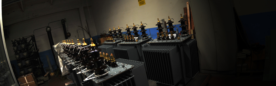
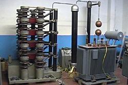
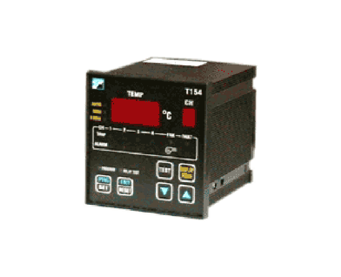
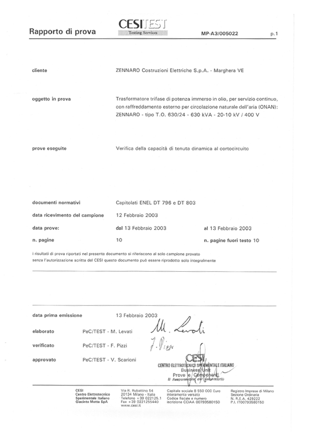
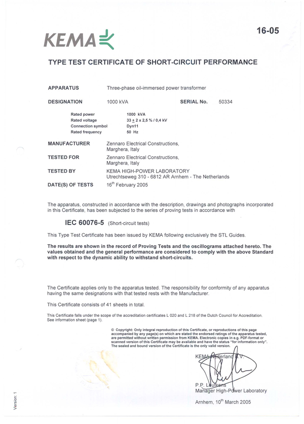
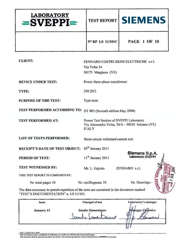
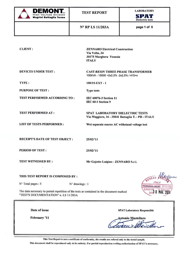
In testing room, the transformers are subject to a series of measurements and tests.
The client and/or a representative can request to witness the test.
Once the routine test is complete, the protection instruments and other accessories are fitted and the transformer is subject to a final general check. Subsequently, the rating plate (stating all data standards requirement) is fixed to the tank.
Instructions for use and maintenance are enclosed with the transformer. The transformer now is ready for packing and transportation.
Since the beginning, Zennaro® has always concentrated on constant quality upgrading in all sectors: production, technology and organisation.
Our quality management system has been assessed and registered as meeting the requirements of ISO 9001 as per enclosed certificate n°IT97/0180 issued on 27/10/1997.
SGS , the certification company , inspects and tests our quality system twice a year.
Quality control manual and procedures manual consisting of more than 1000 pages are available in italian language. The statement of our management as listed is translated here below:
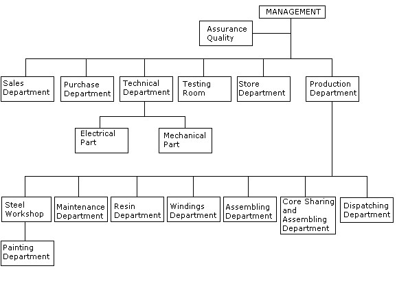
The management of ZENNAROTRAFO, thought it necessary to initiate, maintain, prove with documents and carry out a quality system complying with his own ethic and main national and international standards. Inside the company, the quality assurance division, whose duties are listed below, has been established to assure application and maintenance of rules forming the quality system:
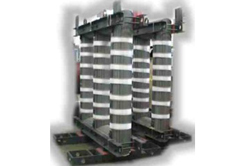
Zennaro® Transformers are manufactured with cores according to the latest knowledge in design, production and materials.
60 years of experience, continuous research and development, assure that Zennaro® transformers can operate with elevated guarantee under different critical conditions.

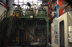
The high technology of our casting plant, the care taken in making the moulds, combined with the high quality raw materials used, enable Zennaro® to produce the highest quality cast resin coils.
The standard of the plant, the control system software, and particularly the epoxy resin allow Zennaro® to obtain a high level product under constant computerized monitoring.
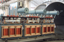
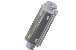
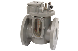
Petersen reactance coil approved by italian electric company (ENEL) consists of reactor adjustable with manual tap changer disconnected from electric system, placed into tank filled with oil containing a current transformer.
TFN and TFNSA are special transformer types, with corrugated steel tank immersed in oil and fit for outdoor use under severe situations.
The winding is zigzag connected to three terminals of network and one terminal for earthing neutral.
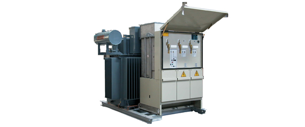
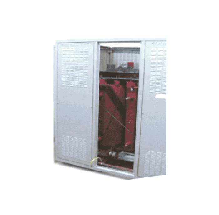
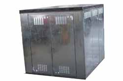
Zennaro® package substation is an integrated secondary transformer unit; It consists of : Housing, made of steel sheet; Ring Main unit of metal stainless steel enclosure; Feeder pillar available in wide range of capacities up to 1600A.
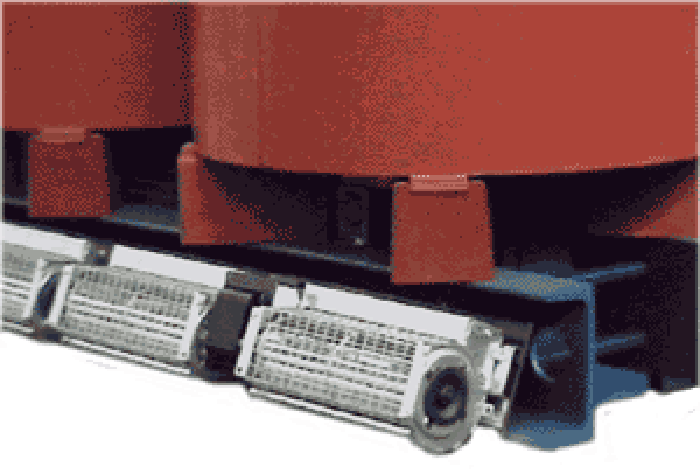
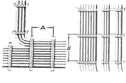
The many installations carried out in a great number of different industries have shown that the UZV cable holder can bring about a 50% saving (as a result of the following): 1) Compared to the traditional method, twice the number of electric cables can be installed in the same underground passage. 2)The amount of steel bracketing required is reduced to about one half.
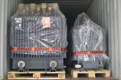
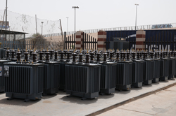
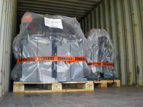
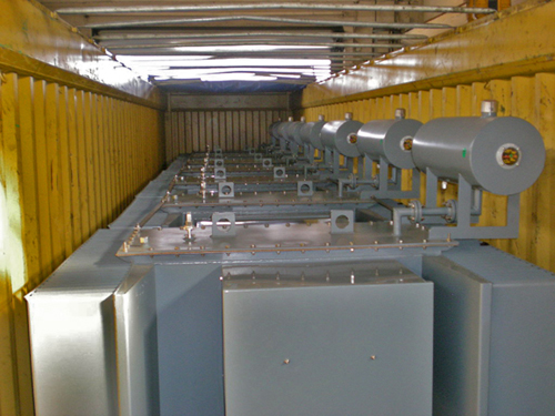
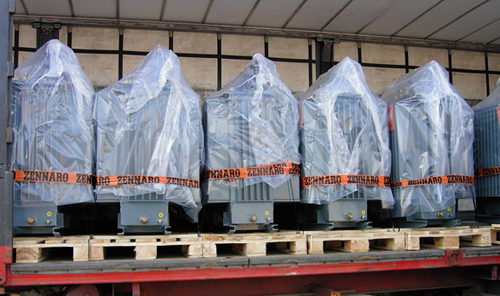
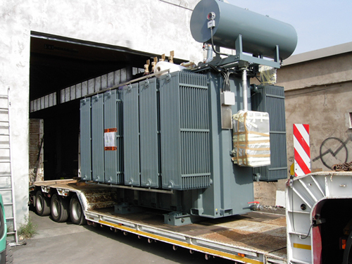
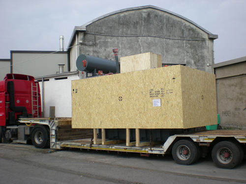
Transformers are delivered ready to be installed, filled with insulating liquid and all accessories fitted.
Adequate packing and securing will be provided. Transformers will be palletised, secure in containers by road, sea or combined transport.
The following accessories (depending on size and specifications) are provided:
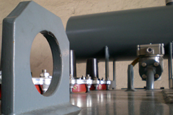
For moving the transformers: a set of rollers, which can easily (depending on size and specifications) be fitted longitudinally or transversally. Lifting lugs over the main cover for lifting by bridge crane. A special support at the bottom of the tank for moving the transformer by forklift.
ZENNARO® transformers may be stored indoor or outdoor.
Before storing a visual inspection is recommended.Check:
All damaged parts, must be replaced or repaired before storage, if necessary oil should be topped up.The transformers may now be stored. No further inspection is required while the transformer is in store.
If the transformer stay in store for long time, before put it in service, a complete check should be performed.
The client is responsible for a proper storage.
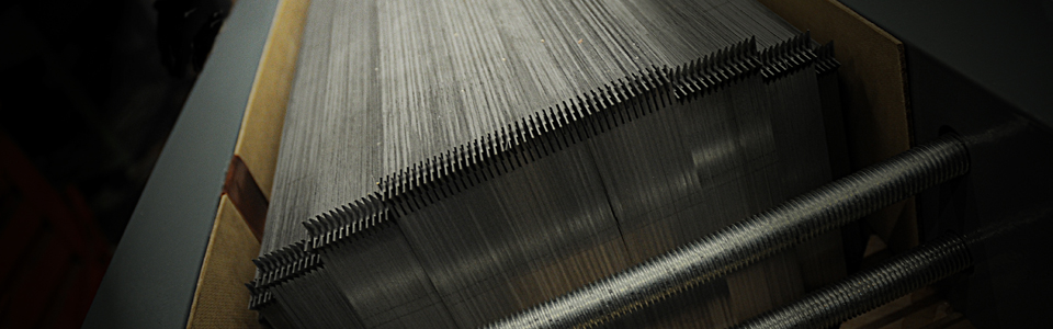
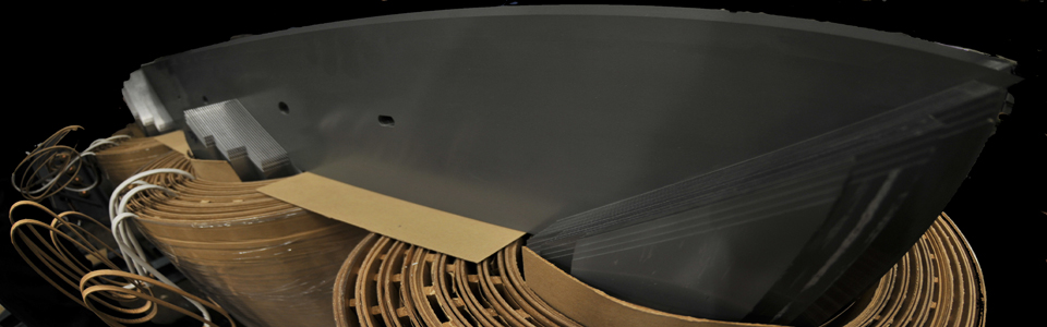
Zennaro® transformers are manufactured with cores according to the latest knowledge in design, production and materials. The core is constructed with columns of sheet cold-rolled, grain oriented magnetic steel and insulated from each other with carlite. The core, completely mounted, is blocked so as to reduce vibrations to a minimum, guaranteeing a low noise level.
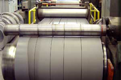
Conventional grain oriented steel (CGO steel) is used for transformers with normal no-load losses, while transformers with reduced no-load losses are built using higher quality HiB steel.
These steel sheets are usually 0.27 mm and 0.30 mm thick.
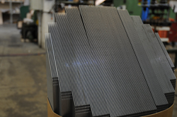
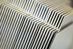
 The core sheets are cut at an angle of 45° in order to maximize the magnetic flux linkage.
Then the sheets are stacked in layers of either single or multiple overlaps. The multiple overlap or step-lap method offers additional benefits in terms of lowering no-load losses and noise levels.
The core sheets are cut at an angle of 45° in order to maximize the magnetic flux linkage.
Then the sheets are stacked in layers of either single or multiple overlaps. The multiple overlap or step-lap method offers additional benefits in terms of lowering no-load losses and noise levels.
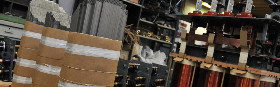
Once the sheets are stacked, the core is compressed and fixed. The majority of ZENNARO® oil filled transformers are produced with oval-shaped core section obtained combining a round shaped section (that offers an excellent short circuit withstand capability of the windings) with a square mid section combined.
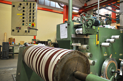
The high grade of the windings underline the quality of Zennaro® transformers. On load during continuous duty they may be stressed by electromechanical effects, caused by short circuit and overloaded by particular needs of network.
60 years of experience, continuous research and development, assure that Zennaro® transformers can operate with elevated guarantee under different critical conditions.
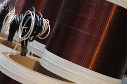
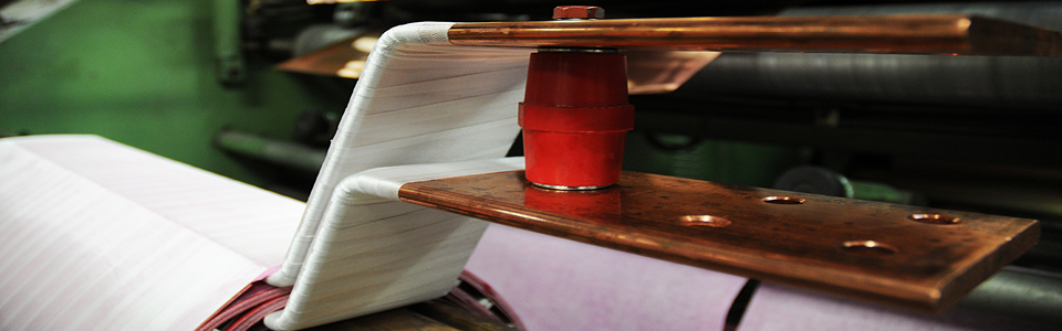
The high voltage windings are almost exclusively made of layered construction. The copper conductors are made of one or more round or square wires, completely insulated by pure cellulose paper or by double enamel. The insulation between the layers consists of pre-coated kraft paper, applied in sheet form.
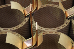
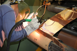
The low voltage windings are almost made of copper sheet conductor (foil); this reduces the axial stresses produced by short circuit to a minimum. The sheets and connectors welded onto them are made of electrolytically pure copper with a rigorously guaranteed conduction. The maximum voltage between each turn is only few volts. This allows the insulation needed between the turns (foils) to be limited to 1 thermo-hardening epoxy adhesive which cures and bonds during the drying process.
Oil channels are provided in order to secure sufficient cooling and avoid the overheating of the winding.
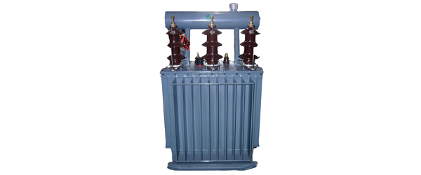
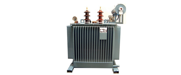
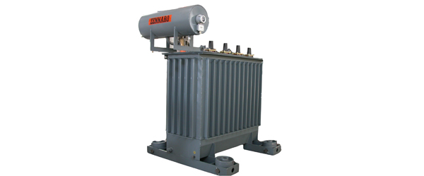
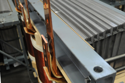
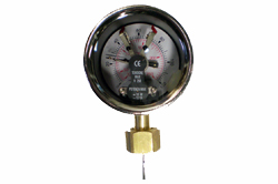
The majority of distribution transformer tanks are constructed with cooling fins. The demand for panel radiator type is limited. Radiators are requested and recomended for transformers of nominal power above 10 MVA. The tank has to withstand all the mechanical strains during transportation and on load during continuous duty of the transformer. Furthermore in hermetically sealed transformers, the cooling fins are designed in order to withstand also the internal pressure occurred during the treatments and oil filling under vacuum. The breathing type transformer has the conservator fitted on the cover. This cylindrical conservator is an expansion for the oil-tank when the windings heat up and often is fitted with oil-level gauge, silica-gel breather in order to ensure that only dry air atmospheric pressure can come in contact with the insulating oil.
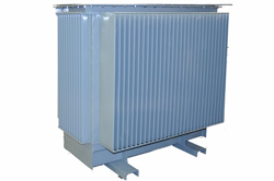
The tank is shot-blasted to remove any scale, oil or other surface impurities, leaving a clean prepared surface for maximum adhesion of the paint coating. Air-drying paint is then applied by spraying or flooding. The tanks are varnished in a powder automatic equipment by means of a first washing treatment with high-efficiency polyvalent phosphor-degreasing liquid, a subsequent coat 70 micron thick of epoxy resin primer and a final coat of thermosetting powder 100 micron in thickness in colour of RAL scale, polymerised at 180 °C. The tanks get a good appearance and an outside agents strength. The tanks may be hot-dip galvanised upon request. This is often requested for transformers constantly exposed to the elements, for pole-mounted or platform-mounted transformers
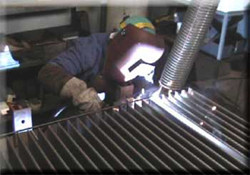
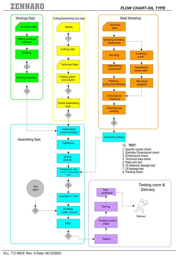
The E-shape cores and the windings from their various departments are moved to the assembly area. The windings are pushed over the core legs and wedged up to fill the spaces between the core and winding as much as possible. Interleaving the laminations of the upper yoke with the laminations of the core legs completes the magnetic circuit. The bushings are mounted on the cover, which is then fixed onto the assembled active part. The next step consists of connecting the windings to the bushings. The transformers are often fitted with an off-circuit tap changer. This tapping switch could increase or decrease of a certain number of turns while the transformer is disconnected from the electric system.
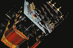
A second tap changer could be mounted on the transformer when is requested a double high voltage level. The voltage ratio of the active part is then tested, and the active part assembled is dried in a forced air oven to remove the moisture from the insulating materials. Once the active part has been dried in the forced-air oven, it is given a final comprehensive quality inspection and placed into the tank. The top cover is then either bolted or welded onto the tank.
The transformers are placed in a vacuum chamber and filled with pre-treated oil (filtered, dried and degassed) under deep vacuum. This ensures optimum impregnation of the insulation materials by the oil, giving the insulation structure maximum dielectric strength. The transformers are filled with a high quality mineral oil, which fully complies with the requirements of IEC 60296 standard.

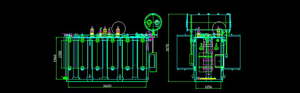
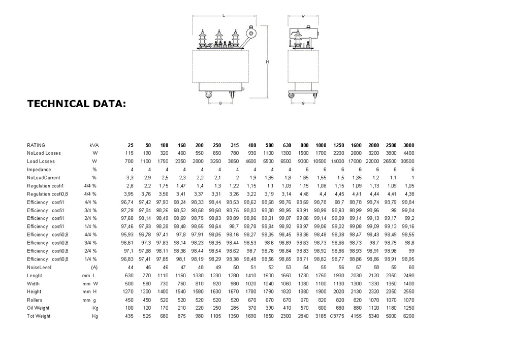
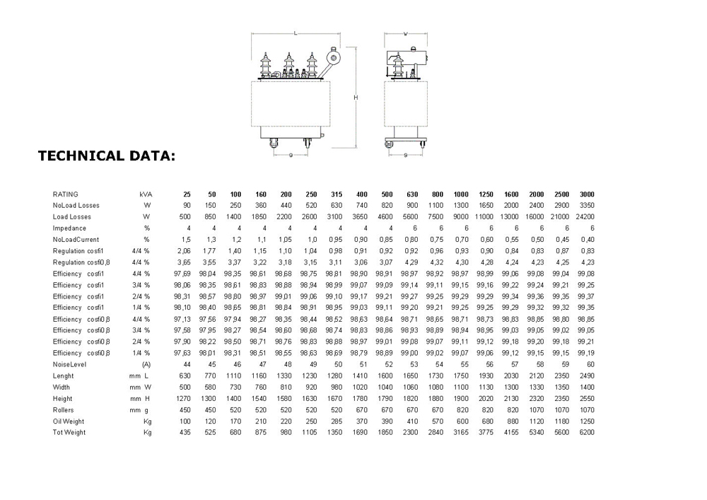
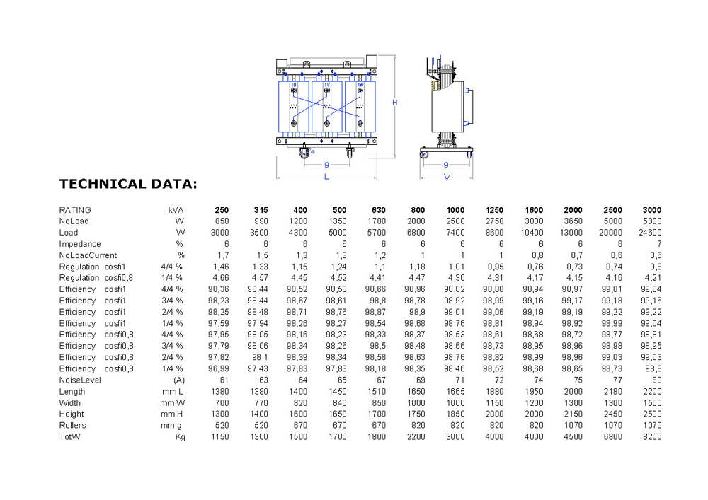
The data sheets contain information about the technical data of the transformers. These information regard dimension and weight data and losses value.
Zennaro® transformers are manufactured with cores according to the latest knowledge in design, production and materials. The magnetic circuit is the core type with its section inscribed in a circle and with inserted couplings. It is constructed with positioned crystal transformer core electrical sheets, annealed in a continuous furnace and insulated from each other with carlite.
Conventional grain oriented steel (CGO steel) is used for transformers with normal no-load losses, while transformers with reduced no-load losses are built using higher quality HiB steel.
These steel sheets are usually 0,27mm and 0.30 mm thick.
The core sheets are cut at an angle of 45°, thus allowing maximum magnetic flux in the rolling direction. Then the sheets are stacked in layers of either single or multiple overlaps. The multiple overlap or step-lap method offers additional benefits in terms of lowering no-load losses and noise levels. Once the sheets are stacked, the core is compressed and glued to form a firmly bonded whole.
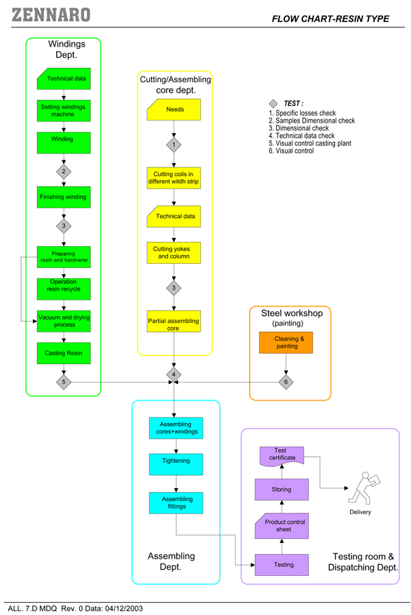
The high voltage windings are made out of copper/aluminium and are so designed to avoid that thermal expansion causes slips between conductors and resin. They are carried out so as to effectively resist stresses caused by short circuit. The method of manufacture guarantees a perfect distribution of the electric field, no partial discharges as well as an excellent resistance to impulse stress. Guarantees have also been planned to resist the external dynamic effects of short-circuit. The dielectric materials employed (resin, conductors and insulators) are class F or H. The transformer has a working temperature rise limit of 100°C (Class F) or 125° (class H).
The low voltage windings are obtained from copper/aluminium with the same height of the primary limb to reduce to a minimum the axial strain due to short circuit currents. A class F or H insulating block insulates the coils. Before mounting, the LV windings are immersed in alkyd resin and then polymerised at 150°C. This process guarantees excellent resistance to external agents (humidity and pollution of the atmosphere). The winding is designed and made out so that the maximum working temperature rise at full load is equal to class F (ΔT=100°C) or class H (ΔT=125°). The concentric shape of the two windings (HV and LV) is maintained by special spacers supports, which allows the supply flux to be uniformly distributed and avoids the onset of abnormal vibrations.
The high technology of our casting plant, the care taken in making the moulds, combined with the high quality raw materials used, enable Zennaro® to produce the highest quality cast resin coils. The daily tests carried out to verify the level of partial discharges in the coils and measure the glass transition TG coefficient, underline the high quality manufacture of Zennaro® cast resin transformers.
The epoxy resin used by Zennaro® is class F and H thermal stability and the product is manufactured in conformity with the temperature limits given by the IEC 60076-11 standards.
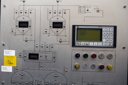
The standard of the plant, the control system software, and particularly the epoxy resin allow Zennaro® to obtain a high level product under constant computerized monitoring. The resin used in the casting system is an epoxy resin charged with very fine quartz powder, giving the transformer the necessary characteristics to pass successfully every test. The computerized monitoring ensures the accurate control of all phases of the process, from the preparation of the resin to the temperature control in the polymerisation stages and to the corresponding TG measuring.
The data sheets contain information about the technical data of the transformers. These information regard dimension and weight data and losses value.
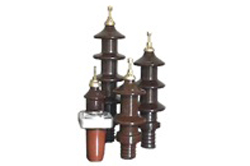
BFZ 1PETERSEN REACTANCE FIXED COIL APPROVED BY ITALIAN ELECTRIC COMPANY (ENEL)
Reactance fixed coil manufactured according to the latest IEC 60076-6 are usually intended for use in M.V. substation.
The value of earthing reactance could be adjust with a manual off load tap changer (range and step on request) depending on the value of rated short time current.
Reactance coil (i.e. Petersen fixed coil) is preferably intended for M.V. network but installation on networks with lower voltage level could be effected, in this case current is consequently reduced.
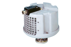
TFNZ 1TRANSFORMER FORMING NEUTRAL APPROVED BY ITALIAN ELECTRIC COMPANY (ENEL)
Earthing / Auxiliary transformer manufactured according to the latest IEC 60076-6 create phisically a star neutral point in medium voltage due a zig-zag primary windings connection in order to be connected with an arc suppression coil (i.e. Petersen Coil).
Hermetically sealed, with conservator or cast resin type could be manufactured on request according to the value of rated neutral short time and continous current. A secondary auxiliary winding in low voltage could be added according to the rating power needed for feeding auxiliary sistem.
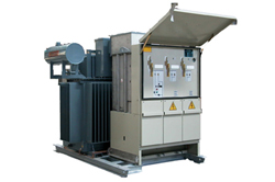
Zennaro® package substation is an integrated secondary transformer unit; It consists of:
The housing, made of steel sheet, is designed for normal outdoor service conditions, so as to protect the substation from external influences and give a specific protection degree against approach or contact with live parts and against contact with moving parts.
RMU consists of a metal stainless steel enclosure. The enclosure is mounted in one structure, made of stainless steel and TIG welded. The enclosure, filled with sulphur hexafluoride (SF6), is designed to withstand internal overpressure and external mechanical loads, without suffering significant distortions.
Moreover, it guarantees gastight. A safety valve prevents potential dangerous overpressure due to faults inside the enclosure. In compliance with IEC 60694 standard, it is sealed pressurized enclosure, assembled and tested in factory; gas treatments are not necessary during the lifetime of switchgear. The switches and all the required equipment for correct running of the switchgear, are located inside the enclosure. Feeder pillar is available in wide range of capacities up to 1600A. Feeder pillar is made of robust varnished corrugated steel sheet.
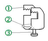
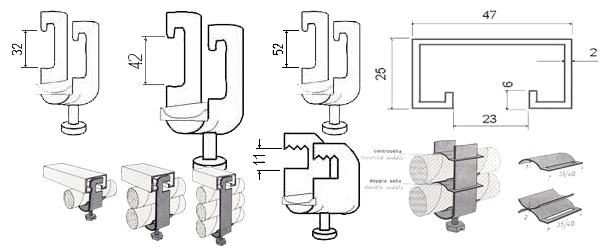
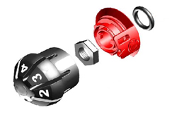
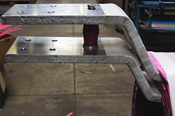
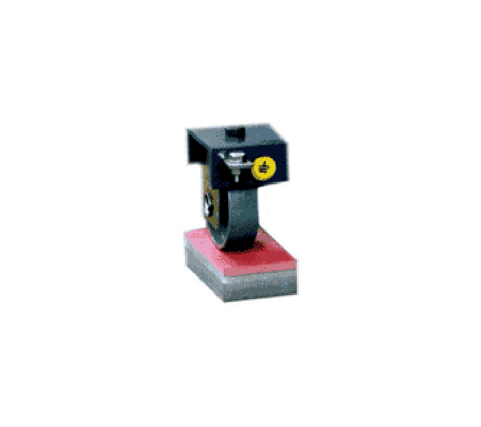
The UZV cable holder consists of three very simple parts:
The installation of the electric cable is carried out in the following three easy steps:
The AISI 430 steel cable holder is suitable for the installation of multipolar cables of any type, diameter, and carrying capacity, as well as, unipolar cables whose carrying capacity is limited to 500 A. In the case of unipolar cables carrying more than 500 A, the use of AISI 304 steel cable holder is recommended.
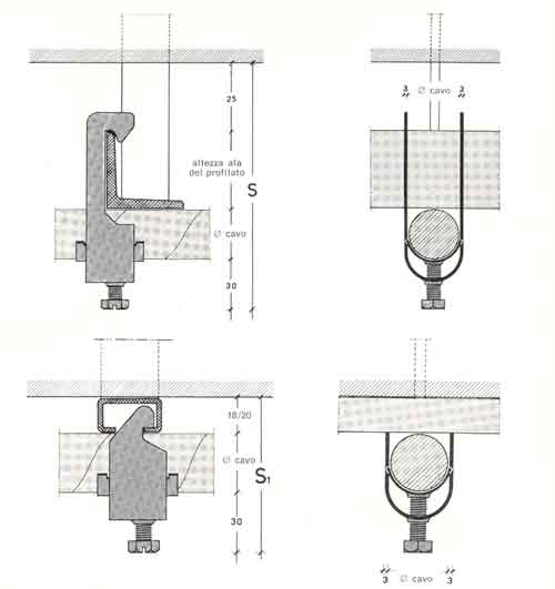
The dimensions of the cable holders are given by clicking in the following figures, while their weights are shown in the relative tables. The choice of the cable holder application depends on the space "S" or "S1" available. The type of section bar used determines the overall dimension of the cable holder.
When ordering cable holders, state the number of each type of cable holder required and the dimension of the supporting section bar, mentioning the side onto which the cable holder is to be mounted
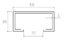
To said bars there is to be added the special section bar we have designed and built for said purpose. Our special bar is particularly recommended when cables are to be installed in very limited spaces and a maximum moment of inertia of the supporting bar is required. The above bar, which is hot-galvanized, is usually supplied in 2 meter lengths.
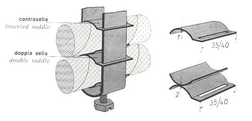
They are both complementary to the UZV cable holder and are particularly recommended when cables with resilient sheathing are installed together. In fact, the inverted saddle prevents the top cable from coming into contact with the supporting bar, while the double saddle keeps the cables apart.

Over 60 years of production in the transformer's market has allowed Zennaro® to expand into several countries in the world. Starting from small business in Italy during fifties, Zennaro® has developed new contacts that allowed to enter the electricity networks in many countries of Europe, Africa, Middle East and South America.
The constant search for new customers and new solutions have enabled the company to deal with new challenges. Being able to win them.
ZennaroTrafo is situated in Marghera, the industrial area out of Venice.
In any case, we suggest you to call us before coming, in order to arrange the best way to pick you up.